
 Ελληνικά


Digikeijs DR5000 DIGICENTRAL MultiBus Central Unit
230,00 €
DCC Multi-bus central Unit
Out of stock
Description
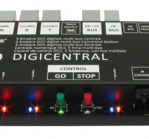
The first central with all imaginable connectors combined in one device. Clear LED displays and integrated USB, LAN and WIFI
DR5000 Multi-bus central features
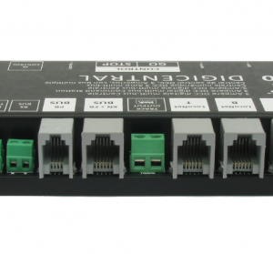
Connection options:
Standard:
USB
– Communication with computer/control program;
– Protocol L.NET or XpressNet V3;
– Virtual COM-port, speed 9600, 19200, 38400, 56800 of 115200 Baud.
– Firmware updates
L.NET T
– Interface for L.NET devices (Controllers, Feedback modules etc.)
L-NET B
– Interface for L.NET devices: (manual-)Controllers, Feedback modules etc. Max 12v/1000mA power;
– Interface for L.NET devices including boosters (rail-sync). Max 12v/600mA power;
X-BUS/R-BUS
– Interface for XpressNet devices: MultiMaus, LH100 etc. Max 12v/1000mA power;
– Interface for R-BUS feedback modules.
B-BUS
– Interface for ROCO Boosters, e.g. the MultiMaus boosters 10764 lan as a booster together with the DR5000!
bereden
RS-BUS
– Interface for Lenz-RS-Bus feedback modules.
ext88N
– Interface for s88N feedback modules. Max 16 x 16 input modules (256 inputs);
– Interface for DR502xEXT modules (bi-directional).
Track-Output
– DCC rail-output. Max 19V/3.2Amp. Lower voltages by other power supply. Min 14V.
Program-Track
– DCC programming output. Max 19V/800mA.
Automatically switches from Track-Out to Program mode so the programming rail can also be used.
LAN
– 100baseT Ethernet. Can be connected to a local network via DHCP.
WiFi/WLAN
– bgn Wireless network via internal antenna.
– Both networks can be accessed via UDP / IP and TCP / IP;
– Protocols: Lenz XpressNet and/or L.NET-TCP/IP;
– Wifi/LAN settings can be changed via a web-interface;
– The WiFi / LAN module can serve as an AP (access point) as well as a router between the DR5000 and WiFi home network (LAN).
Control:
Stop
– Disable Rail output.
Go
– Enable Rail output
IR-Throttle
– IR receiver compatible with Uhlenbrock IRIS and Piko DigiFern (or other RC5/36Khz remotecontrols).
– 4 channels, per channel directly to be controlled/switched, 1 lok and 4 switches.
– Further control possible through X-BUS and/or L.NET (manual)controls,
the DR502xEXT modules or via the USB/LAN/Wifi interfaces.
LEDs:
STATUS
– Power: Power supply present; Programming track indicator
– Load: Ouput load. Intensity is increased with the load.
off = no load, on is is 3.15Amp;
– Short: Short circuit. Blink Code defines the bus caused the short circuit;
Continue on is Track-Out
USB
– TX: Data is sent to the computer;
– RX: Data is received from the computer.
INFRARED
– RX: Valid IR data is being received.
X-BUS
– TX: Data is being send to the X-BUS
– RX: Data is being received from the X-BUS.
STOP
– The signals to Track-Out and the booster connection are off.
GO
– The signals to Track-Out and the booster connection are ON.
L.NET
– TX: Data is sent to the L.NET;
– RX: Data is being received from L.NET
ext88
– There is at least one input on the s88 bus active;
Intensity increases with the number of active inputs.
WiFi
– Active: The Wifi Network is active.
LAN
– Link: The LAN is connected and connected to a switch / hub / router.
ROUTER
– Status: The internal router is active.
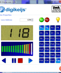
DCC:
Locs
– 126 simultaneous operation / control of locs;
– F0 – F28;
– 14/28/128 levels;
– Long and short addresses. (9999 for long, Maximum short addresses to be set from 0-127)
Switches
– 2048 switches;
– Offset +4/-4 for MultiMaus compatibility
General:
Feedback
– 2048 feedback, which is the total of all possible buses.
A smaller maximum could occur per bus
– Feedbacks from combining all buses in one series of 1-2048
Protocol conversion
– All protocols are translated to the DR.Cmd internal protocol.
Every Bus/Connection receives specific and relevant data from the internal protocol.
Power Supply
– Modern, low-loss switching external power supply.
Additional information
| System | DCC 2rail |
|---|